Engine power loss, emergency landing, and rollover
VIH Helicopters Ltd.
Kamov Ka-32, C-GKHL
Bella Coola, British Columbia, 25 nm E
The Transportation Safety Board of Canada (TSB) investigated this occurrence for the purpose of advancing transportation safety. It is not the function of the Board to assign fault or determine civil or criminal liability. This report is not created for use in the context of legal, disciplinary or other proceedings. See Ownership and use of content.
Summary
The VIH Helicopters Ltd. Kamov Ka-32A11BC, (registration C-GKHL, serial number 31594) was carrying out fire suppression operations using a water bucket on a long line connected to the helicopter's external load belly hook. At about 1830 Pacific Daylight Time, just after the helicopter lifted a load of water out of a high altitude mountain lake, there was a loud bang followed by howling and grinding noise, and the helicopter began to shake severely. The pilot not flying released the external load (line and water bucket) and the pilot flying flew towards land for an emergency landing. The crew had difficulty keeping the helicopter pointed in the direction they were tracking, and the shaking was such that they could not see the instrument displays. The helicopter touched down while drifting sideways to the right with near-full left cyclic control input. The helicopter bounced and rolled onto its right side, and the main rotor blades contacted the ground and broke. The crew was able to shut down the engines and exit the aircraft with minor injuries. There was no fire. The 406 MHz emergency locator transmitter activated upon touchdown.
Factual information
History of the flight
The accident occurred on the second day of operations at this location near Bella Coola. The lake into which the crew were dipping the water bucket was at about 5500 feet above sea level (asl). The helicopter was able to lift a full bucket of water weighing about 3200 kg at the beginning of each fuel cycle.Footnote 1 The fire they were fighting was downhill from the pick-up lake. The time between each water drop was about 5 minutes. There were no extraordinary flight profiles required to douse the fire.
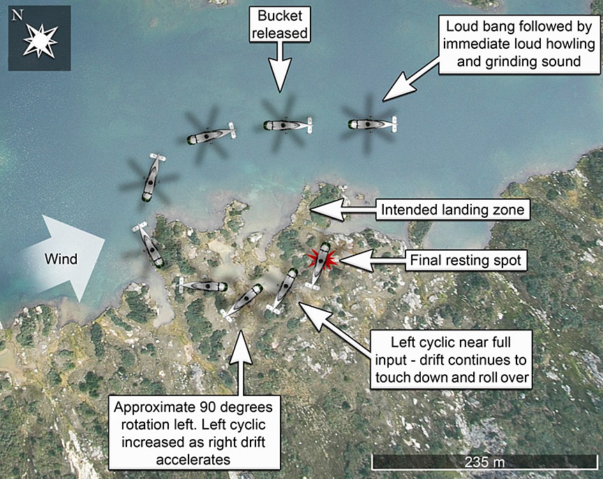
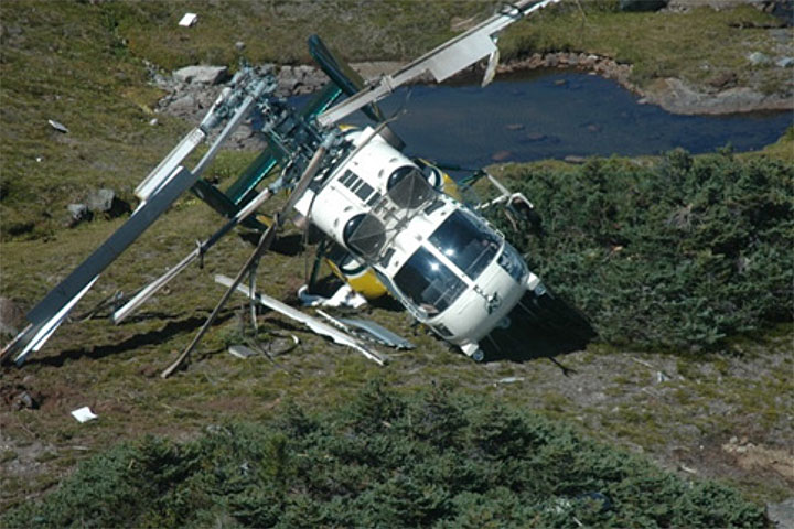
On the second water pick-up during the third fuel cycle (Figure 1), the helicopter hovered into wind over the lake picking up water. As the crew lifted the bucket out of the lake, there was a loud bang and the helicopter began to shake excessively. The helicopter became difficult to control and descended towards the lake. The pilot not flying (PNF) released the water bucket, and the pilot flying (PF) was able to arrest the descent. The crew could not see the instruments due to the vibrations, and determined they had a problem with the rotor system. The PF flew the helicopter to the nearest place thought suitable for an emergency landing. The approach was down wind, the terrain was not level and the PF was not able to maintain the helicopter's heading constant. On touchdown, the helicopter bounced and landed on its right side (Photo 1). The rotors were turning at normal speed − about 270 revolutions per minute (rpm) − when the blades collided with the ground and broke. The energy in the broken blade pieces caused some of them to travel several meters from the main wreckage.
The crew shut down the engines and evacuated the helicopter without difficulty. They used a satellite telephone to alert the company. The company's satellite tracking system provided the helicopter's track and final location; the crew was picked up by another helicopter working in the area.
A cursory examination of the damaged helicopter by one of the company's aircraft maintenance engineers (AME) revealed damage to the left side engine (No. 1 engine) that was consistent with turbine failure before the helicopter's hard landing.
Flight data recorders
The helicopter was equipped with a flight data recorder (FDR), but not a cockpit voice recorder (CVR). Neither is required by regulations when carrying out aerial work operations. The FDR was removed from the helicopter and the data was reviewed by TSB investigators with help from the operator's technicians and the Russian based Air Accident Investigation Commission, Interstate Aviation Committee (MAK).
FDR data revealed a sudden loss of power from the No. 1 engine, followed by a loss of main rotor rpm. Both alternating current (AC) generators dropped off-line during the time the rotors were below normal operating rpm. Low rotor rpm was only brief, and the AC generators came back on-line when the rpm returned to normal after the load was jetisoned. However, the AC powered autopilot system shut off and, as designed, did not come on when AC power was restored. The FDR data also show that after the power loss, the No. 1 engine continued to operate at low rpm until it was shut down.
The engines' turbine operating temperatures (TOT) were not recorded on the FDR because the input had been disconnected during unrelated maintenance troubleshooting.
Weather
The weather in the area was suitable for visual flight rules (VFR) flight, with clear skies, unlimited visibility, winds at about 15 knots from the west and an air temperature of about 15°C at the accident site. The density altitudeFootnote 2 at the accident site was about 6800 feet asl.
The company
VIH Helicopters Ltd. (formerly Vancouver Island Helicopters) was founded in 1955. In the early 1990s, the company acquired a limited type certificate from Transport Canada (TC) to operate Russian made Kamov Ka-32A11BC heavy-lift helicopters. These helicopters are operated in Canada and internationally to carry out heavy lift work for seismic, mining, forestry, and other special lift operations. The company has its own aircraft maintenance organization (AMO) with technicians trained to maintain all of its helicopters. Major component overhaul for the Russian helicopters was carried out by the component manufacturers in Russia and the Ukraine.
Pilots
There were 2 pilots operating the helicopter; both were qualified to act as captain. Records indicate that the flight crew was certified and qualified for the flight in accordance with existing regulations.
The PF had about 14 800 hours total flying experience in helicopters, of which about 4200 hours were acquired flying the Kamov Ka-32 type. The PF had completed the required recurrent ground and flight training on the Ka-32, including engine failure emergency procedures.
The PNF had about 19 200 hours total flying experience in helicopters, of which about 4300 hours were acquired flying the Kamov Ka-32 type. The PNF had completed the required recurrent ground and flight training, including engine failure emergency procedures.
Both pilots were within the flight and duty time limits prescribed by regulation, and fatigue was not considered a factor.
Neither pilot had previously encountered vibrations or noise similar to those encountered during the accident sequence.
Aircraft
| Manufacturer, type and model | Kamov Кa-32А11ВС |
|---|---|
| Year of manufacture | 1992 |
| Fuselage length | 11.30 m |
| Height | 5.40 m |
| Main rotor diameter (each) | 15.90 m |
| Maximum take-off weight (w/external load) | 12 700 kg |
| Maximum external (under slung) load | 5000 kg |
| Maximum flight speed (Vne) | 140 knots (102 knots with external load) |
| Engines (2) Klimov TV3-117BMA | 2200 hp each |
| Total time since new (TTSN) | 17 318.3 hours |
| Maintenance – 16 000 hour inspection | 16 254 airframe hours, 7 November 2011 |
| Maintenance – 25/50/100 hour inspection | 17 251 airframe hours, 21 June 2013 |
The helicopter's No. 2 engine was replaced on 02 August 2013 at 17 308 airframe hours. As a result, flight tests had been carried out, and power assurance checks on both engines showed normal performance.
Records indicate that the aircraft was certified, equipped and maintained in accordance with existing regulations and approved procedures.
Flight control systems
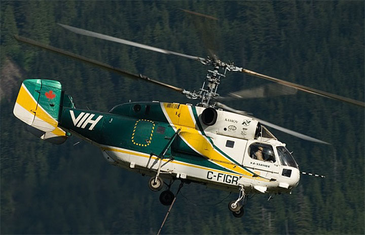
The Kamov Ka-32A11BC has counter-rotating rotors (2 main rotors, stacked on top of one another, turning in opposite directions; see Photo 2). There is no tail rotor; the torque from the upper rotor offsets the torque from the lower rotor. To induce yaw, torque to one rotor is increased while torque to the other rotor is decreased; total lift remains the same but the aircraft will yaw in the direction opposite to the rotor with the higher torque. This system is most effective when torque is high. The vertical stabilizers, with their rudders, help the pilot maintain yaw control when there is sufficient forward airspeed; however, yaw control is minimal at low power and low airspeed.
The Ka-32 is equipped with a control augmentation system referred to as the autopilot. This system operates on AC power generated from the rotor transmission. The AC generators operate in a narrow rpm range (normal rotor rpm) and are tripped off when the rpm drops below 83%. Without AC power, the autopilot drops off-line and larger control movements are required to change the helicopter's attitude. It should be noted that although the AC generators will automatically come back on-line when the rotor rpm returns to normal, the autopilot must be re-engaged by the pilots.
Weight and performance
The helicopter was being operated within its weight and balance limitations at the time of the accident. The gross weight of the helicopter was 11 639 kg with the water bucket full, and 7784 kg once the water bucket was released.
With one engine inoperative (OEI) at the operating weight of 11 639 kg, a density altitude of 6800 feet, and hovering with the water bucket a few feet over the lake, the helicopter could not attain a safe fly-away speed and would descend until the weight of the water bucket was removed, either by it landing in the water or being released. Once the weight of the water bucket was removed, the helicopter should have been able to climb at 275 feet per minute, using the 2.5 minute OEI power limit and 32 knots indicated airspeed.
No. 1 engine maintenance
| Manufacturer | Motor Sich (Ukraine) |
|---|---|
| Engine model and serial number | Klimov TV3-117BMA |
| Year of manufacture | 1989 |
| Total time since new (TTSN) | 5124.2 hours |
| Time since overhaul (TSO) | 1110.3 hours |
| 1st major overhaul by Motor Sich | TTSN 1443.6 hours in 2000 |
| 2nd major overhaul by Motor Sich | TTSN 2690.1 hours in 2006 |
| 3rd major overhaul by Motor Sich | TTSN 4013.9 hours in 2010 |
In August 2011, when it had accumulated 4283.5 hours of total time since new (TTSN), the engine was inspected and repaired by Motor Sich (Ukraine) because metal particles were found in the oil.
In April 2013, at TTSN 4936.9 hours and 923 hours time since overhaul (TSO), in accordance with Transport Canada's Foreign Airworthiness Directive RU-2012-53-05Footnote 3, the compressor turbine was replaced with another compressor turbine (different part number) with 956 hours TTSN and 0 hours TSO. The fuel manifold was also replaced with another (different part number) which had 956 hours TTSN and 0 hours TSO. Also at that time, 7 new T-102 thermocouples were installed.
The engine was installed in C-GKHL on 16 May 2013. On 18 May 2013, the engine's maximum power caution light started activating inconsistently. The caution light sometimes activated before the engine reached maximum power, and sometimes failed to activate when the engine reached maxium power. The electronic engine governor (EEG-3) was replaced; however the problem was not resolved. On 19 May 2013, the fuel control unit (FCU) was replaced, and the problem was resolved. During that time and until the engine failure, several power checks demonstrated that the engine's automatic limitation system was functioning correctly and that no engine limits were exceeded.
Examination of failed engine
The helicopter was recovered from the accident site and transported to a facility where it was examined, and the No. 1 engine was removed for disassembly and detailed examination. Before the engine was removed, standard tests were carried out by an avionics technician to determine the functionality of the engine turbine temperature indicating system. The results of the tests showed that the electrical resistance in the system circuits was within the required range for proper temperature indications. This also confirmed that the disconnect of TOT input to the FDR had no effect on the functioning of the gas temperature limitation system.
Fuel and oil filters were examined; there were no extraordinary findings.
The power turbine (PT) section was separated from the rest of the engine, and examinations revealed damage consistent with damage from objects upstream.
Further disassembly exposed the compressor turbine (CT) section. Examination of the CT section revealed that all the CT blades were broken off, and that several of those were broken close to the blade roots. Very few of the turbine blades' broken pieces were recovered; the turbine exhaust showed damage consistent with turbine blade debris exiting with the exhaust gasses before the engine stopped.
The CT blades were removed from the section turbine hubs and examined under optical microscopes and scanning electron microscopes (SEM) to determine fracture surface structures that demonstrate failure modes. All of the available fracture surfaces were consistent with overload failures; therefore, those fracture surfaces were not the origin of the initial failure.
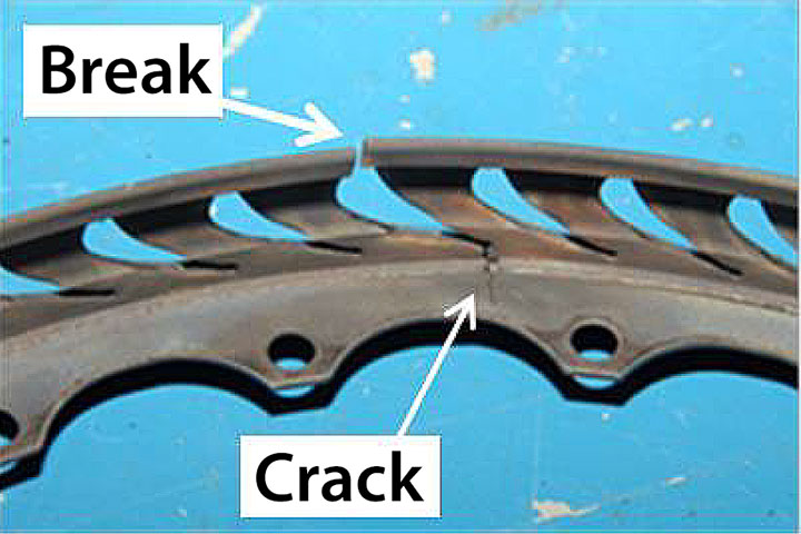
It was also apparent that the ring that retained the first stage guide vanes for the CT section had failed on its outer edge and cracked on the inner section of one of the guide vane slots (Photo 3). The fracture surface features were consistent with a fatigue break.
The CT blade parts, the CT section guide vanes, the guide vane retention rings, the CT wheel hubs and the thermo couplings for the engine temperature indication system were sent to the TSB Engineering Laboratory.
Selected CT blades were sectioned and examined under SEM to determine material structure and composition, and their exposure to higher than normal operating temperatures. Very little microstructural changes from the root to the tip of the blade were observed for each of the CT blades examined. However, there were considerable variations in the microstructure from blade to blade. This suggests variations in the heat treatment during manufacture rather than in-service heating. Neither the engine manufacturer nor the engine designer provided the investigation team with design standards for material structure of the CT blades.
It was determined that the CT blade fracture surfaces were caused by overload. However, it was noted that some of the remaining parts were short enough that some of the blades could have broken more than once (e.g., a blade may have broken at two thirds of its length and then been hit by debris and broken again at one third of its length).
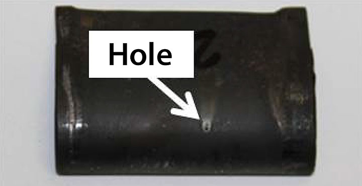
All but one of the guide vanes demonstrated normal in-use wear (some erosion and material separation). The exceptional guide vane had a small hole on its low pressure side (Photo 4). Microscopic examinations revealed that the hole was not manufactured. These vanes are designed with holes on the high pressure side that allows charged air to exit on that side for temperature and airflow control. Air exiting on the low pressure side will cause unanticipated turbulence in that area of the engine.
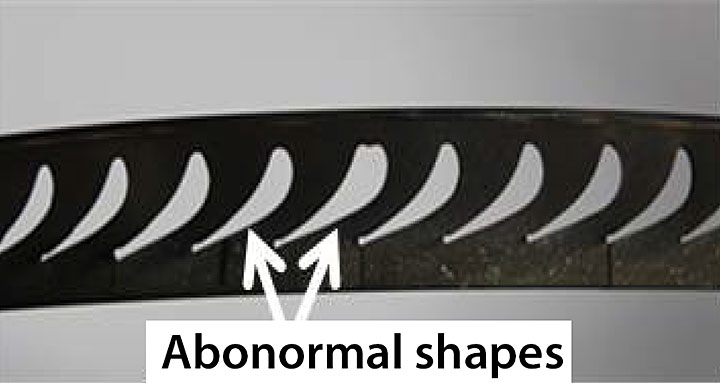
The guide vane retention ring, which has slots the guide vanes fit into, showed anomalies in the size and shape of the slots (Photo 5). Microscopic examinations revealed that the slots had been machined to different shapes during manufacture, rather than worn into these different shapes.
TSB Laboratory reports
The following TSB Laboratory report was completed, and is available from the TSB on request.
- LP204/2013 – Examination of engine components
Analysis
Except for the density altitude which affected initial aircraft performance, weather conditions at the time did not contribute to the accident. The following analysis focuses on human factors, the aircraft's performance, the engine failure, and quality control of the engine components during manufacturing and assembly.
Engine failure
FDR data showed that the No. 1 engine lost power during flight. Examinations determined that 1 or more 1st stage compressor turbine (CT) blade(s) broke and subsequently collided with the remaining blades, causing them to break. All of the blades in the CT section broke, and all of the blades downstream in the power turbine (PT) section were either broken or damaged. As a result, gas flow was reduced and power was lost. The turbines continued to rotate at reduced revolutions per minute (rpm), causing vibrations because of unequal blade damage. The low rpm of those turbines caused the vibration signatures to be inconsistent with normal engine vibrations.
Detailed examinations of the CT section components revealed manufacturing anomalies. While the lack of information from the manufacturer limited the TSB's ability to compare the accident engine blades to a standard, large differences in material structure can be caused by treatment variations during manufacture, such as heat treatment or coating regimes. Such variations are not likely to have been within a design standard. Poor quality control during manufacture can allow components like these to be installed in an engine.
The material structure anomalies that were found are consistent with variations in the heat treatment during manufacture, and reduce resistance to failure. Additionally, the anomalies in the 1st stage guide vane retention ring would have allowed the guide vanes to move and warp, thereby causing unanticipated gas flow patterns within the compressor turbine. This likely caused the fatigue cracking and breaking of the retention ring. This, combined with the anomalies in the material structure of the CT blades, likely caused one or more of the CT blades to fail. Furthermore, the hole on the low pressure side of one of the guide vanes may have added to the gas flow pattern changes.
Emergency landing
The helicopter was hovering at a high gross weight when one engine lost power. This is a critical phase of flight as high power is required. In this occurrence, the majority of the load being carried was hanging externally on a 150-foot long line below the helicopter. When the engine lost power, the helicopter descended and the load landed in the lake and was released, thereby removing about 3855 kg of the load. Because the helicopter was still 150 feet over the lake and the power required to maintain flight was substantially reduced, the remaining engine provided sufficient power to restore rotor rpm and allow the helicopter to be flown away from the lake. However, because of the following factors, the crew did not identify the problem as an engine failure and did not shut down the failed engine: the presence of severe vibration, which was greater than either pilot had ever experienced, the lack of visual clues caused by the pilots' inability to read the instruments, and the poor control responses. The severe nature of the vibration could have been indicative of an imbalance in a major and critical rotating component, such as the rotor system or transmission. For these reasons, the crew executed an emergency landing on the closest land surface.
During the emergency landing, the crew had difficulty controlling the helicopter, particularly its heading. The landing surface was uneven, and the helicopter was still moving over the ground partially sideways upon touch down. This caused the helicopter to roll onto its side enough to allow the rotor blades to strike the ground.
Quality control
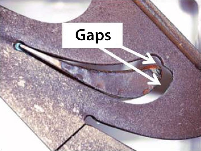
The manufacturing anomalies in the guide vane retention ring slots were clearly visible to the naked eye. These anomalies, which show up as gaps, were even more evident when the guide vanes were installed (Photo 6). The guide vanes should fit in the slots tightly; there should be no visible gaps. The fact that obvious anomalies like these were missed during the manufacturing and assembly of the engine components may indicate a problem with quality control. If poor quality control in the manufacture and assembly of Klimov TV3-117 helicopter engine components is systemic, helicopters with these engines are at risk of failure, which can have serious consequences for aircraft, crew, and passengers.
The anomalies in the structure (alloy treatment) of the CT blades were also likely due to poor quality control during the manufacture of these blades. This too puts personnel involved at risk, as these anomalies on their own could cause blade failures.
Findings
Findings as to causes and contributing factors
- Anomalies in the manufacturing of the compressor turbine section components in the No. 1 engine caused failures in those components, which resulted in a loss of power.
- Quality control during the manufacturing and assembly of the engine's compressor turbine section did not identify these obvious anomalies.
- The severe vibrations and sloppy control responses caused the crew to carry out an emergency landing on rough terrain, which resulted in the helicopter rolling onto its side and the rotors striking the ground.
Findings as to risk
- If poor quality control in the manufacture and assembly of Klimov TV3-117 helicopter engine components is systemic, helicopters with these engines are at risk of failure, which can have serious consequences for aircraft, crew, and passengers.
Safety action
Safety action taken
Type certificate holder
The regulator (Russian Authority) that holds the engine type certificate issued Revision 1 to Airworthiness Directive (AD) RU-2012-53-05R1Footnote 4 on 11 November 2013. It requires Klimov TV3-117BMA engines installed in Kamov Ka-32 helicopters used for external load operations to make the following changes:
- All engine cycles will be multiplied by a factor of 1.2 (this means that the engine life limits that are measured in cycles would be reached 20% sooner); and
- Upon engines reaching 750 hours since overhaul, the parts installed at this mid-life “hot section” inspection will now be new. This also now applies to these parts at engine overhaul.
The AD did state that the investigation of the failure in Canada was still in progress and that the changes would not be final until the results of the investigation were finalized.
VIH Helicopters Ltd.
- VIH Helicopters Ltd. has increased the “Load Release” training and added it to the yearly recurrent training requirements;
- The company is field testing an improved electrical release guard that allows easier access to the external load release button in the Ka-32s they operate.
This report concludes the Transportation Safety Board's investigation into this occurrence. the Board authorized the release of this report on . It was officially released on .
